|
Hubo Library
|
|
Hubo Library
|
Hubo hardware is an assembly kit extending GPIO functionality of many small micro computers (e.g. the Raspberry Pi). Hubo hardware provides the following hardware features:
Hubo makes use of common chips like the MCP32017 and the MCP3208 (the MCP3008 is also supported) thus allowing for being controlled by third party libraries too. When designing the board special care has been taken to support for robustness against electromagnetic noise as well as allowing for an easy assembling of the kit.
Since Hubo hardware is build on SPI and I2C bus communication it works with many mini computers and micro controllers. However, there are a number of those that have explicitely been tested.
Raspberry Pi models:
Banan Pi models:
Please provide your feedback if you have been using Hubo hardware on other boards than the ones listed above.
Hubo Library is developed under Raspbian Linux using the C-runtime for device communication. Thus binaries of the library can be used on mini computers running the same processor architecture. The library has positively been tested on Raspbian (Jessie) images released for the above hardwares. Please note that the GPIO support is currently limited to the SoC's that are shipping with the Raspberry Pi. Thus GPIO support for the Banana Pi is not yet available.
Hubo Library provides support for the following hardware:
Additional features like raw data access, event handling, oversampling and others are not subject to the hardware and therefore are always supported.
Well - you don't have to but you can. If you're happy using 3rd party Python libs (and there are many around) then simply continue using those. If you've been using Python already for controlling similar hardware then you could adapt one of those 1000 scripts and control Hubo hardware by those libraries and scripts. You would not even need to install py-spidev or python-smbus while it is already present on your machine. So in most of the cases you're fine with other software too when controlling Hubo hardware. For more information please see How to use Python..
Hubo library was designed with the same idea in mind which was also the base for designing Hubo hardware. It is easy to use still protecting multi threaded applications from typical pitfalls such as deadlocks, bus collisions, starvation through a poor design of arbitration, race conditions, data integrity problems and others. Hubo library on the other hand gathers as much "soft real time behaviour" that can ever be expected from a none real time kernel such as the commonly used Raspbian operating system. A background heart beat (the so called cycle time) allows for periodic tasks at a high priority. Callback handler will inform if the system load gets too high hence violating the time keeping of the cycle tick. Background operations are executed under RT scheduling policy using the highest priority available.
Low level BCM2835 GPIO support allows for bit banging protocols directly through the GPIO pins. While these functions are also protected by a mutex avoiding race conditions - the mutex can be turned of allowing for high performance IO up to several MHz.
All in all Hubo library introduces a simple to use interface which due to its structure allows for the implementation of applications that require a strong time alignment of the software (such as controllers). All this is guided by multi threading protection Hubo library provides for your application - something many other libraries do not do.
So if you're looking for a robust yet easy way to access Hubo hardware - this library will do the job for you.
Connect the Hubo hardware to your Raspberry Pi and activate the Raspbian kernel modules required. Raspbian does enable the device tree option by default but have SPI and I2C options disabled. This will prevent the library to run. Use the "advanced" menu entry of raspi-config to enable these options.
If you want to use the 1wire functionality then you also have to enable GPIO pin 4. Edit /boot/config.txt and add the following lines to it:
You are now ready to run the precompiled demo applications provided with the library or create your own applications.
There are install scripts /home/pi/HuboInstall/install (for the Raspberry Pi) and /home/pi/HuboInstall/bpi_install (for the Banana Pi) that will allow for a seamless installation of Hubo Library. Existing files will be backed up with the extension of _original. In order to install on a Raspberry Pi please run:
For the Banana Pi run:
Note - running these scripts several times will overwrite copies created in prior runs of the script.
It is strongly encouraged to update the installation of your Raspbian OS. This is done automatically by running the installation script. Otherwise run the following commands manually:
The easiest way to understand how to use Hubo library functions is to run the demo applications and follow the code. At a first glance there's nothing to do as the demo applications are pre-built already. However, if you like to modify one example ore want to recompile it then there are shell scripts called build in each folder. Simply call the script to re-build one or all of the demo applications.
If you haven't done it already you can install the compiler by running the following command.
If you follow the samples in the given order you'll get an introduction on how to use the library functions but you'll also learn about timing constraints, CPU usage, potential deadlock situations, how to get more resolution from your ADC, make use of digital input change events and much more.
Whenever you run a demo application or one of your applications make sure you're running them as sodoer! If you fail to run the applications with the appropriate rights the library will fail to initialize.
Take your time to step through the samples in order to get most out of your hardware.
Last but not least - some tiny little helper.
When talking to a piece of hardware then this is fine as long as you are the only one who wants to access it. But as soon as two people are trying to use it in parallel the trouble starts. Who will get the access granted? How long will that be for? When will access be granted to a long waiting process? So whenever hardware (or any other mutual exclusive resource) gets shared, these kind of things need to be considered. Different techniques are applicable. You could of cause implement a mutex that manages access. Placing some kind of arbitration around will overcome starvation. But what about timing? Let's assume one person requires to regularly printing pages - maybe every hour. However, one of those days a huge printing job gets started in-between by person two - breaking the hourly sequence of person one. Bad luck. Person one can do nothing but wait until the person two has finished printing. The same happens when applications want to access hardware e.g. an ADC or an IO Expander. Protecting hardware through mutexes ensuring data integrity and avoiding packet collisions is good as long as timing doesn't matter. Once it does matter this simple concept of synchronisation is not sufficient anymore.
Therefore any hardware IO requested by an application using Hubo library is buffered and performed by a background thread. Hence applications are not directly accessing the hardware but accessing buffered data only. A high priority background thread (running at a RT scheduling policy with the highest priority possible) is capturing data from the hardware while also writing new digital values down to the IO expander.
By doing so the background thread is exclusively using the hardware - thus not running into the problems of concurrent requests of a multi threaded application. When several threads of an application try to read and write data they only read from and write to internal buffers - operations that are executed fast in time. Hence the chance of an interference of those threads amongst each other is also kept to a minimum.
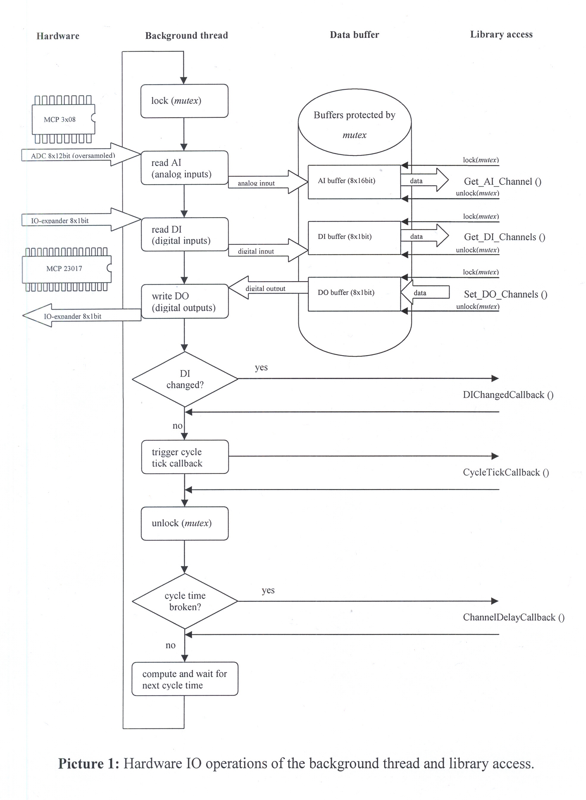
Picture 1 illustrates the internals of data processing performed by the background thread and the accessing of the data by an application using Hubo library. When starting a new cycle - the background thread locks any access to the data buffers. That will prevent other threads of an application from reading data while it is updated at the same time. It also ensures that the entire IO area (digital and analog input and the digital output) is processed nearly in the same time. Thus ensuring data integrity.
If a callback handler for digital input change is installed it will be called soon after the data exchange with the hardware has been completed. Note that the mutex (which is protecting the buffered data) is still locked while performing the callback functions. That means while executing the digital input changed event callback function this function can still safely access the data in the buffers. Also note that just like any other registered callback function this function also gets executed in the context the background thread - hence the same priority. In almost all cases this will mean that your application will remain blocked from execution while your callback handler gets executed! See the demo SampleCallbacks.cpp for more information on this topic.
Once the event handler for digital changes has been called, the normal cycle tick callback event will be raised. This gives an application the chance to get notified on each cycle the background thread walks through. The callback will receive pointers to any of the IO buffers. Similar to the event changed callback function this function should not be used for lengthy operations.
The last callee executed by the background thread is the channel delay event. It will always be called when the background thread notices that the execution is delayed for at least one cycle tick or more. Why's that? When trying to implement a controller (e.g. a PID controller) you require an accurate timing calculation and cannot afford to drift over time. The background thread takes care for this timing and - if detecting a delay - will notify a registered application of such a delay. Note that the mutex is not locked anymore when executing this callback. This allows an application to gain back some time to the Linux scheduler e.g. by calling usleep(). For a better understanding of the Linux scheduling internals refer to the Linux man pages (sched_rt_period_us, sched_rt_runtime_us...).
An application in contrast is accessing the buffers by one of the calls for digital or analog IO access. Such a call will first lock the mutex protecting the buffers prior to accessing the data. Note that accessing the data this way is safe, but provides data integrity only at the level of the call itself. If you really require to latch digital and analog data exactly at the same time then use the cycle tick callback and perform a copy of the data provided by the buffers. Keep using this copy for further processing. However, in most of the cases this will likely not be necessary.
The answer to this is pretty simple. Just as fast as your application needs it to run - but not any faster!
If for example you're only interested in digital input and its changes you could run the background thread with a cycle time of up to 1000Hz (1kHz). However, you'll notice quite a bit of CPU usage that is spend only for performing the background thread retrieving the data. Trying to run the thread at any higher frequency would not work well as most of the time would then be spend in the Linux kernel for scheduling your thread - not for processing your data. Also you'll see that it will not be possible to retrieve any analog signals from the ADC. In order to do so you'd need to lower the frequency of the background threads cycle tick. At 100Hz (10ms) for example it is possible to latch any of the digital and analog inputs while also performing changes on the outputs. The CPU usage will still be acceptable in order to allow other applications to run smoothly.
Ok, I'm only measuring temperature data that does not need to be done that fast at all - so 1s should be enough?! Maybe. It depends whether you'd like to also gather digital inputs in parallel at a higher speed. Detecting fast changes e.g. from a push button might require you to poll at around 20Hz even though your temperature sensors might be happy to run at 1Hz. You need to take a choice here! Hubo library does not allow you to run IO operations at different cycle ticks (apart from cascaded Hubo slave modules).
Why's that? Simply in order to guarantee stable operation over the time. If you'd for example run digital IO at 100Hz and analog input at 10Hz each 10th cycle the background thread would have to do more work than within the other 9 cycles. For a guaranteed cycle tick this is not good. However, once you've thought about the timings of your application you'll most likely find a suitable cycle time for having the background thread performing all of your IO operations.
There are many ADC boards out in the field that offer far more than 12bit of resolution. Are they better than this 12bit ADC that gets supported by the library? That question cannot easily be answered. Sure, a few more bits of resolution never hurt. However, resolution without precision, calibration, absolute or relative linearity does not help much. If for example the reference voltage which comes along with quite a high precision catches noise from the power supply - then the ADC will pick up that noise and your measurement is imprecise. If the analog connectors of your board are not shielded against noise you're likely to see the low bits of the ADC toggling. An ADC itself comes with its own linearity - specified by the manufacturer. How many bits undergo the linearity error? Sure, you can calibrate your ADC - or even better - the entire path (starting at the sensor ending at the ADC) and then you'll get this extra precision. But you really need to do that and also need the equipment to do so. In fact that's essential if you'd not only gain the extra bit of resolution but also precision! One last word about the signal to measure. What's the source that's supplying the current for the sensor? Is this supply stable enough to have the sensor produce an accurate signal? If not then the entire measuring might be limited to the power supply of your sensor.
To cut a long story short. Resolution is good but sometimes overestimated. The hardware controlled by the library was designed to be quite robust against noise coming from switching power supplies - for the sake of not sampling at the highest speeds the manufacturer of the ADC would allow for. However, there are other limitations such as the Linux scheduler that limits you to even lower speed (around 500Hz). Still the hardware is able to get you signals toggling only for 1 LSB (that is around 610µV) of the ADC while switching relays in parallel. What's that? Well, when switching relays quite a bit of current will be eaten up by the coils of your relays. A board design that does not take this into account is likely to suffer a drift of the ground potential.
Still interested in oversampling? In standard operating situations the hardware can provide you with a resolution of the quality that is also specified by the manufacturer. Therefore a good base for oversampling is given.
If you like to oversample analog input signals then this can be specified by a call to Set_MCP3x08_Oversampling(). In fact this call also determines what channels to acquire at all. Channels to be (over-) sampled are specified by an array passed in. The array would contain a value of 0 for not sampling the channel, 1 for a single sample or any other count to oversample that channel for the number of times as specified. Of cause there are limits to the number determined by the number of channels to be sampled, their oversampling counts, the cycle time and the load of your CPU. Check the return value of et_MCP3x08_Oversampling() to see whether the call succeeded and set up a callback handler (Register_ChannelDelayCallback()) in order to get informed of broken cycle ticks at runtime. Also note that oversampling requires to take the frequency of the signal to measure into account. Therefore you might want to perform your own oversampling within your own application.
Once projects grow there might be a need for additional digital inputs or outputs. In order to address these requirements Hubo supports cascading (chaining) of the digital modules. Through cascading a Hubo master can add up to 3 additional slave modules adding to the total number of 32 digital inputs and outputs. When a slave module gets cascaded a jumper specifies its I2C address on the bus. By calling GetSlaveDeviceList() a list of these addresses is returned. An application should refer to the index which points to the specific address in order to invoke its reading and writing operations. In general all slave operations are very much the same as their master module counterparts. So when calling Set_DO_Channels(0x12) on a master would result in an equivalent call to Set_Slave_DO_Channels(0,0x12) in order to perform the same output (0x12) on the first slave found on the I2C bus.
While the cycle time defines the update interval the background thread polls the hardware for new data and sets new output values a slave module can define a cycle tick divider in order to skip the potentially high update rate of the master. This is useful in cases where some of the digital IO should run at a lower frequency or CPU time should be saved. While the default value of g_I2CConfig.m_MCP23017SlaveCycleTickDivider is set to 1 (leading to the same update interval as specified for the master) the value can be increased. Setting a value of 4 will result of updating the slaves every 4th cycle time tick.
In order to avoid bus collisions the reading of new slave values is performed right after the master values have been read. Vice versa writing to slaves occurs right after the slave outputs have been updated.
Note that one can also equip a Hubo master module with the jumpers to select the I2C addresses. By doing so the digital IO part of the Hubo master module can be treated as a slave module itself. This can be helpful when the analog part should be run at a high frequency while the digital part does not need this high cycle time. Thus this technique can save CPU time in some cases.
Sometimes it is necessary to track a signal with a high frequency once a certain condition is met (e.g. a threshold got exceeded, an alarm input has triggered). While the cycle time cannot be used for cycle ticks higher than 1kHz (the standard Linux scheduler cannot efficiently perform thread context changes at these high rates) any of the callback routines can be used to call the low level analog data input routine Get_AI_Channel_Raw(). This routine can be called any time soon after Initialize() has been executed. It does not require the cycle time to be set nor to wait for buffers to get filled prior to its call.
Similar to reading analog values digital values can also be read in any of the callback routines. For more information refer to Get_DI_Channels_Raw(). This routine can be called any time soon after Initialize() has been executed. It does not require the cycle time to be set nor to wait for buffers to get filled prior to its call.
Note that the setting of the I2C bus speed heavily determines the speed that can be achieved for digital raw data access. Current Raspbian releases are using 100kHz as a default for the I2C bus speed. Refer to the documentation to change this value in the device tree to adapt it to your personal needs. Experiments have shown that when firing up the I2C clock speed up to 800kHz then the sample time will decrease in a way to allow for up to 10kHz sample speed. However, increasing the I2C clock speed will require lower bus capacitance and is therefore not recommended for usage in noisy environments.
In order to support bit banging protocols directly through the BCM2835 GPIO's Hubo library introduces functionality for configuring, reading and writing to these pins. To retain high flexibility all calls will be executed in the callers thread context. This way an application can determine thread priority, timing and other stuff itself. For an easy use in multi threaded applications a mutex is provided on entry on any of the functions synchronising concurrent access. However, in cases where the overhead introduced by the mutex is not acceptable it can be turned of by a setting in the configuration. Access to the GPIO's is granted directly through reading and writing to the registers of the chip.
For more information please refer to the documentation BCM2835.
Once your Hubo hardware is up and running you'd probably like to test it with the software. In order to avoid any problems refer to the precompiled demo applications provided with the Hubo library documentation. There are however, a few things to consider...
The demo applications abort with assert() messages.
Hubo library requires to change the scheduling policy of its background thread. This as well as the access to the I2C bus and the SPI bus requires special rights. If they are not granted by udev rules then start the application as sudoer.
The C compiler won't compile the application.
Hubo library uses C++ internally thus making use of C++ name mangling. Therefore compile your application with the C++ compiler and linker.
Either access to the analog or digital channels won't work.
Check the Linux kernel drivers to be loaded and the device tree to be parametrised correct. For a quick check you can also disable the device tree by reconfiguring your system (e.g. by using raspi-config).
Taking a closer look at the locking and unlocking mechanism of the data buffers it's obvious that the mutex is locked during the entire period of hardware access. Does that have to be this way? The answer to this is pretty simple - no, it doesn't. In fact the IO operations could all be performed without prior locking and just the update of the data buffers would need to be protected by the mutex. However, it turned out that the hardware access is performed in a very short time not consuming CPU resources - so only a potential callee would be affected and get preempted. Still, room for improvement...
Error handling could also be improved a bit. Currently there are only a few return values that tell about the outcome of an operation. However, there's not much information that would give you some hint what to change in order to get rid of the error. There is for example no check whether the application is run as root. So unless you've set up some udev rules in order to allow a group of users to access SPI, I2C - your application would require sudo.
Hubo is not just a software project. Hubo hardware is a DIN rail compatible hardware that extends the Raspberry Pi for digital and analog inputs, open collector and relay outputs, allows for cascading up to 4 modules via I2C bus and brings in RTC supports through an DS3231 real time clock mounting port. The 1wire bus allows for using several 1wire devices such as temperature sensors and other. Some modules even allow for extending the hardware for 433MHz FM transmitters for controlling RC-switches.
For more information please refer to one of the download links below:
Hubo Hardware
Hubo Hardware Comparison
Download
This software is free for private use for Hubo hardware. Other usage is not permitted. Since the software is free for Hubo hardware, copies of it must also be distributed free of charge. The author does not guarantee the software to be free of errors nor that it meets the users requirements in any way. The user of this software will not claim the author or any person distributing this software for any damage, loss of profit or savings nor any other incidental or consequential damage. The software must not be used in any hazardous environments! It must not be altered in any way and copies must contain all parts of it - including this documentation. No support is granted neither by the author nor any distributer of this software.
V. 2.1.6 - Nov. 2019
V. 2.1.5 - October 2017
V. 2.1.4 - Apr. 2017
V. 2.1.3 - Mar. 2017
V. 2.1.2 - Feb. 2017
V. 2.1.1 - Aug. 2016
V. 2.1.0 - Nov. 2015
V. 2.0.1 - Jun. 2015
V. 2.0.0 - Feb. 2015
V. 1.01 - Dec. 2014
V. 1.00 - Nov. 2014
Copyright © 2018 Dag Auerbach
Raspberry Pi and Raspberry Pi Logo are registered trademarks of the Raspberry Pi Foundation.
Debian is a registered trademark of Software in the Public Interest, Inc. (SPI).
BROADCOM is a registered trademark of Broadcom Corperation and/or its subsidiaries.
Banana Pi and Banana Pi Pro are registered trademarks of Shenzhen LeMeiKe Science&Technology Co., Ltd..
Raspberry Pi und Raspberry Pi Logo sind eingetragene Warenzeichen der Raspberry Pi Foundation.
Debian ist ein eingetragenes Warenzeichen der Software in the Public Interest, Inc. (SPI).
BROADCOM ist ein eingetragenes Warenzeichen der Broadcom Corporation und/oder ihrer Tochtergesellschaften.
Banana Pi und Banana Pi Pro sind eingetragene Warenzeichen der Shenzhen LeMeiKe Science&Technology Co., Ltd..
Impressum Datenschutz
 1.8.8
1.8.8

